05+ Superduty CTIS
I’ll go over my CTIS setup using 05+ superduty unit-bearing axles. The front is functionally no different than a stock superduty axle for the intents of this discussion. The rear is totally different than stock as this is a custom axle that uses front unit-bearings in the rear application. As a result of this, all four corners use the same unit bearing which was nice since once I solved sealing that part, it was done for every corner.

The general idea here is that the hub region of the unit bearing is pressurized, and then we must seal both the axle shaft and the outer hub face from leaking.
This whole system has been through 2500 miles of 75MPH highway to and from Moab and 10+ off-road days. Rears have had zero issues, fronts I was previously using OEM seals that blew out a few days in to Moab but I found a better replacement part noted below.
I’ll go through component by component talking about the sealing technique, then go back and talk about the overall system, solenoids, controller, etc.
Unit Bearings and Hub Air Passage
The first trick to the unit bearing modification is we have to add an air passage radially through the hub. Here’s what we’re ultimately going for to get air out to the tire (I’m not sure if this would work with OEM brakes, and I sort of doubt it! I’m running Wilwood Dynalite calipers which just barely clear this hose as it goes out to the wheel):

To make this passage, I drilled a long hole radially through entire surface of the unit bearing wheel flange. This is then tapped with a 1/16 NPT, which you can get 1/4″ OD quick-connect fittings for.

For the brakes, I just drilled a hole in the rotor hat for the fitting to pass through. You do have to un-screw this fitting every time you take the brake rotor off, but it only takes a few seconds and is no big deal.

Fortunately, the unit bearings require almost no work to seal. The factory axles use the unit bearings as a vacuum seal for their vacuum-actuated hubs, so there’s already seals in there. It is very lucky that these happen to also hold positive pressure, as there’s no particular reason they should since many seals like this are directional. I’m using Moog unit bearings, who knows if any other brand works. If anything, the Moog bearings are actually better at sealing positive pressure than vacuum, so it’s totally possible they designed them poorly which makes them work better here!
There is one little upgrade we have to do. Although the actual seal holds the pressure fine, it turns out Moog did not fully seal the pressed-in bearing seams. I just put some green sleeve retainer in these two grooves (don’t let any of this stuff get into the seal!), then put a vacuum on the tone-ring hole to suck it in if there are any tiny leaks. Let it sit for a few hours, soaked up the excess liquid, and good to go. If you skip this step, you might have a very slow leak (something like 1-2PSI/day). There might be even better ways to do this, not sure if there’s a proper way to seal something like this from the outside.
Even with this rework, I think some of these unit bearings still have an extraordinarily slow leak. We’re talking something like 1PSI/week tire pressure loss or even less. I couldn’t care less but be aware these aren’t necessarily absolutely perfect. They do not dynamically leak, I’ve put entire days on these at 70MPH and never lost even a pound of tire pressure.

Wheels
Wheels pretty much is what it is, ultimately you have to get from that hose on the unit bearing into your wheel. Every model of wheel you’ll have to figure out the best way to accomplish this. I’m running Hutchinson beadlocks which were fairly easy to modify to have a robust accessible connection.
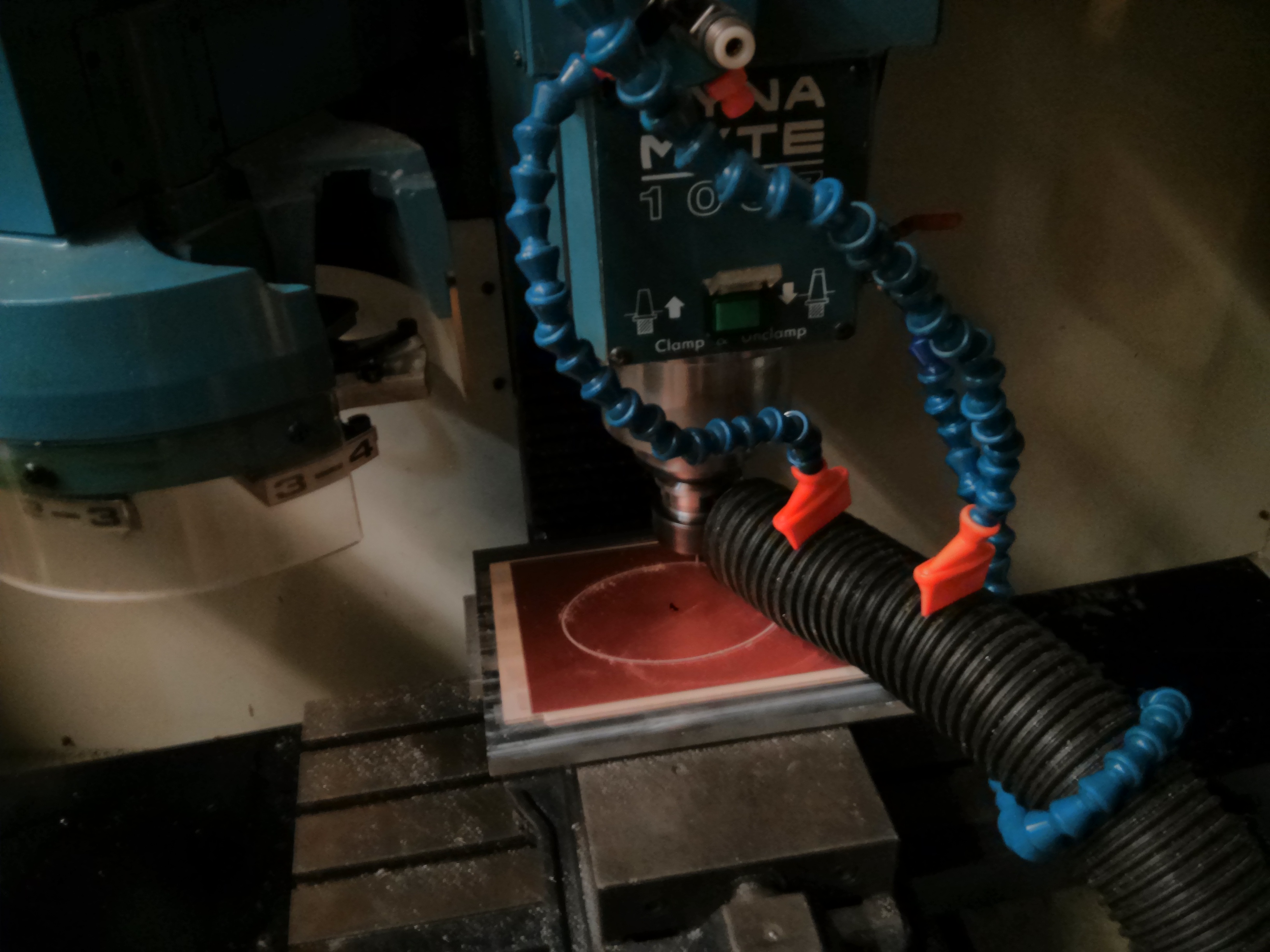
I cleaned up a parallel surface on the inner face and drilled and tapped for 1/8″ NPT facing inwards. I made a little fixture to hold a hand drill perfectly aligned for this as it was not worth setting up fixturing to do this drilling on the mill.
You could also theoretically drill the inside face of you wheel and have it all hidden away. I don’t think I’d recommend this, though, as it’d be quite a nightmare to plug that hose in. It’s very nice being on the outside, and it’s well hidden behind the beadlock bolts of the Hutchinson so it’s very unlikely to get damaged.


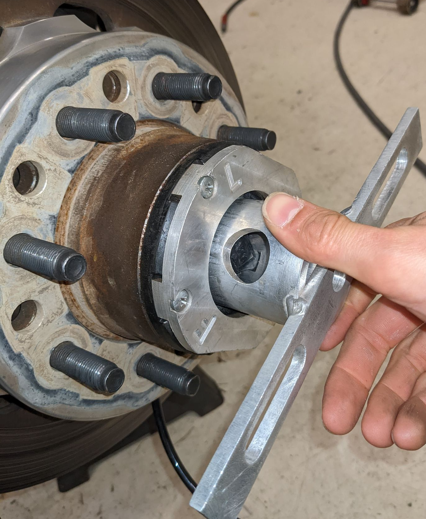
Warn Hub Modifications
I wanted to keep locking hubs, which required some slight modifications. First, you have to groove off one of the splines in the support insert of the locking hub (this isn’t actually a load bearing piece and is just mild steel that’s easy to machine). This will act as an air passage through the hub assembly.

The hardened steel clutch that actually carries the torque happens to already have some missing splines, so no need to make a modification there!
That’s about it for the hub mechanical assembly. When you slide it in, just make sure this missing spline groove lines up with the spline where your bore hole passes in so that air can flow between the hub and the wheel hose. Also line up one of the grooves that already exists in the hardened clutch part.
I’m using Warn locking hubs here, no idea about the OEM vacuum hubs I’ve never even seen one in person. You also have to upgrade the o-ring in the locking hub knob. The stock o-ring doesn’t stand a chance at sealing positive pressure. Took a while to figure out how to get this knob out, if you just keep turning the knob clockwise past locked, it pops right out. Recommend removing the hub first or it’ll probably shoot out at great velocity. Then just put a bigger o-ring on here and it’ll seal up fine.

Then you run into a new problem. When you have air pressure actually pushing this knob out, it jams up because the latching tabs on this aren’t intended to take an outward thrust. They are aluminum on aluminum with sharp edges and immediately cut each other up. As a result, I had to machine these outer plates which I slip two carrier shims into to act as a crude thrust bearing. You have to machine this just right so that it preloads the knob in about 5-10 thou if I remember right to keep force off the locking tabs

The final problem with the locking hubs is that when the thicker o-ring is in there, it’s too stiff to turn by hand. So I made this aluminum tool to actuate the hub knobs and just carry it with me.
Stub Shaft Seal
Now all that’s left to seal up the front is the stub shaft seal. In an OEM application, a vacuum seal takes care of this. You cannot use the OEM vacuum seal, it will not work for positive pressure. You must use the National 710925 seal, which is a strange product as it’s not actually recommended for an 05+ superduty yet it fits perfectly and is better designed. What’s even more remarkable is you install it in the proper orientation as though you’re holding vacuum, and it magically just also works for positive pressure (OEM seals do not, they only hold vacuum).
High Steer Arms
If you have unmodified OEM knuckles then you just use the vacuum fitting port and you’re done. I have a high-steer arm on an OEM knuckle that I milled flat, which was blocking access to the vacuum port passage. To solve this, I just tapped the high-steer arm for a 1/8 NPT fitting and milled a 1″ groove into the back to hold an o-ring which seals against the top of the knuckle:


Rear Axle
The rear axle has fewer sealing points than the front. The outer hub is simply a sealed cap so nothing to do there, and the unit bearing is the same as the front on modifications.
All that’s left is the axle shaft seal. This took a few iterations on attempts but I finally came up with this seal cartridge that fits in to a 2.25″ Seals-It holder so I just removed the old seals and slide this in. It has an x-ring seal and a retainer plate to hold the seal in place. Since my shaft necks down, I have to first put the seal on to the shaft, slide it into the seal cartridge, then put the retainer plate over. The whole cartridge is held in place by 3 set screws that push outward.


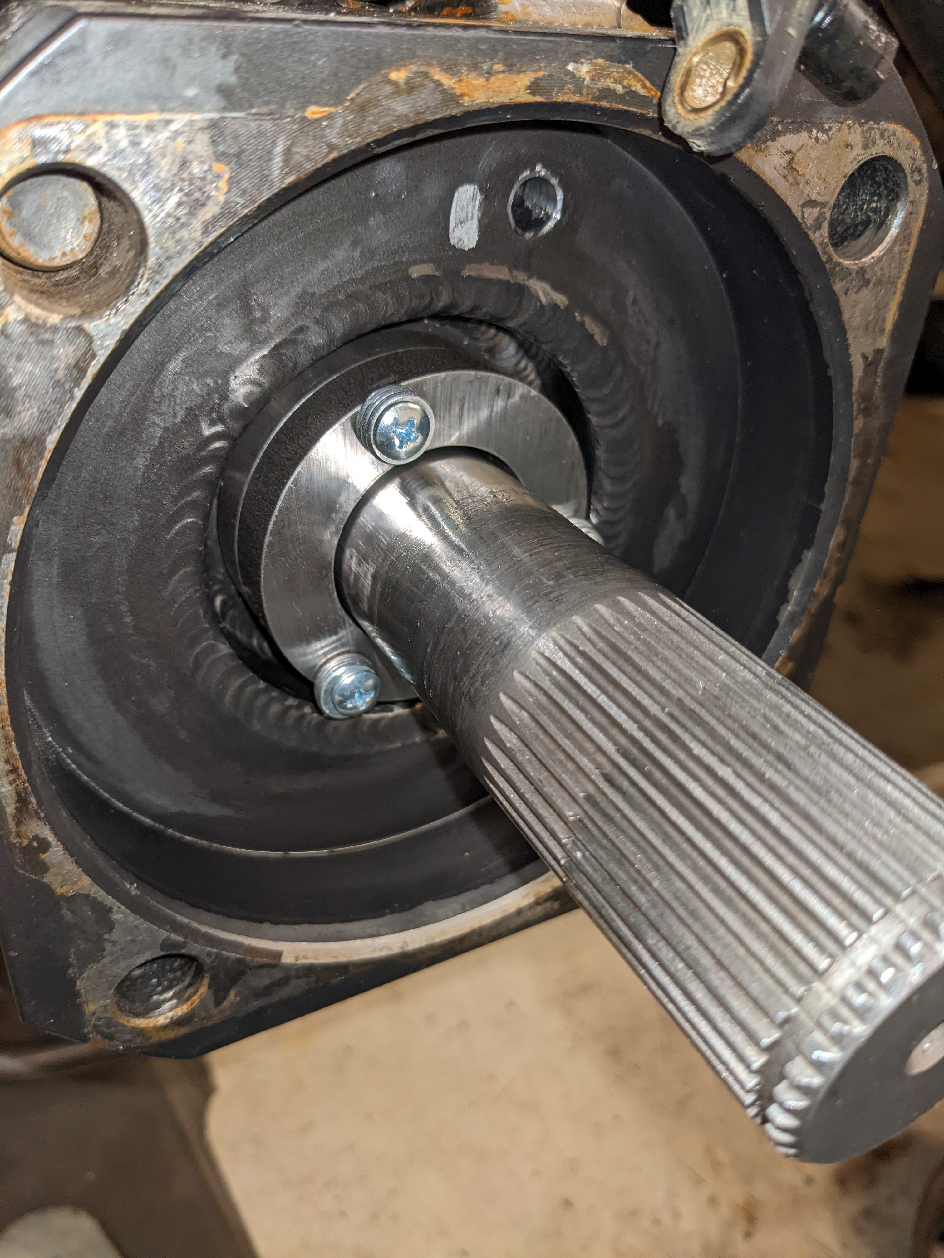
Then to get air in, I just drilled a passage through the unit-bearing cup that’s welded on to the axle. You can see the inner passage coming out in the above picture, and then a hole is drilled through the top with a 1/8″ NPT bung welded above.

The final modification for the rear is you have to take off one spline from the drive slug to allow air to pass through. You line this up with the spline where the radial bore hole in the flange enters the hub chamber just like the front. There’s so much material here and the coarse splines are so huge that I have no concerns about strength with this change.

I don’t have a picture of it, but I also made a spacer and put a c-clip in the outside of the axle shaft to keep it about 1/8″ from bottoming out in the cross pins of the differential. I’m not really sure if it’d be a problem, but there’s about 50 pounds of air pressure force pushing these shafts in and that might eventually chew up the cross pins.
Controls
To control the system, we need solenoid valves connected to each corner to allow for inflation, deflation, or isolation to hold pressure fixed during normal driving. This took some searching to find just the right thing. There is no appropriate direct-acting valve in a reasonable form factor, so we have to use pilot actuated valves. This just means you have to actually have the pump on with a compressed source to even deflate the tires, which isn’t a big deal.
A good solenoid I used in this system is the AVS-523C2-24D available from Automation Direct. I’m sure you could buy a higher quality part that does the same thing, but this one has worked fine for me so far. It is normally-off and spring loaded to return to center, so even with no pressure in the system your tires remain isolated and pressurized. Apply pressure to one coil and it pressurizes, apply pressure to the other coil and it deflates. They even sell a 4-channel manifold block to make it extra easy to hook up. Make sure to hose the deflation path outside the vehicle or you’ll be inhaling incredibly overwhelming tire smell as it deflates inside the passenger area.
I also added a pressure regulator to keep the inrush pressure to about 40PSI max. I don’t want to even find out what happens if you put 150PSI on a vacuum hub seal, so I decided to not check and just add the regulator. I also added an air dryer to the inlet to try to keep as much corrosion out of the hubs as I can.
I mounted all this up on one of my rear strut tower body covers:

Made an aluminum cover and mounted air dryer where it’s easily accessible through the back door:

I also wanted to have a pressure sensor on each tire, so I made a little pressure sensor manifold board containing 4x NXP MPX2202DP differential pressure sensors leaving one side open to act as a gauge sensor. This board has an instrumentation amplifier on each one providing 0-3.3V output across the pressure range to be read by a microcontroller.

The solenoid control lines and pressure sensor signals then route to a custom microcontroller board running an STM32F4 controller mounted under the steering wheel. A bit of a wire mess in here, but whatever it works. This also connects to my OBD port for data collection as well as a serial link to a wideband gauge to monitor and log AFR.

A 3.5″ touch screen connects to this board for an interface. The interface and control firmware is all written in a C program. First, this board acts as a general telemetry display and logger to an SD card:
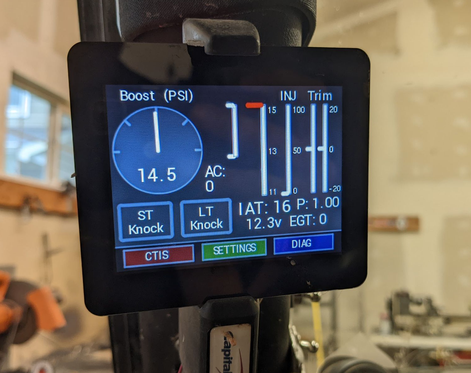
If you go in to the CTIS menu, you can get a real-time reading of all fire tire pressures:

Select any tire or all tires to deflate or inflate, and a keypad appears to type in the target pressure:
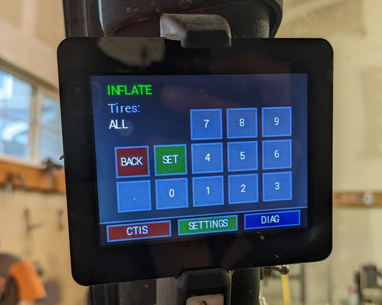
Once you establish a new set-point, the computer automatically runs the solenoids to inflate or deflate, checking the pressure every 2 seconds by briefly turning the valves off just as you would with a manual tire deflation gauge.
I can go from street pressure to 8PSI in about 45 seconds. Inflation is pump limited, just have an ARB twin so it takes some time to get back up. But you can do it on the drive home.
Jeep Sway Bar CAN Hacking
The sway bar in my Jeep can be electronically disconnected, but the engineers decided that it must re-engage above 18MPH and/or in 2WD. I don’t especially like this because I’m often going over 18MPH over very uneven terrain that can benefit from no sway bar.
Some people do things like remove the motor and add a pneumatic actuator, or take out all the electronics and run a switch directly to the motor (don’t press the switch too long or it’ll burn out!). I figured it’d be fun to do it by intercepting CAN messages and modifying them before sending them on to the sway bar.
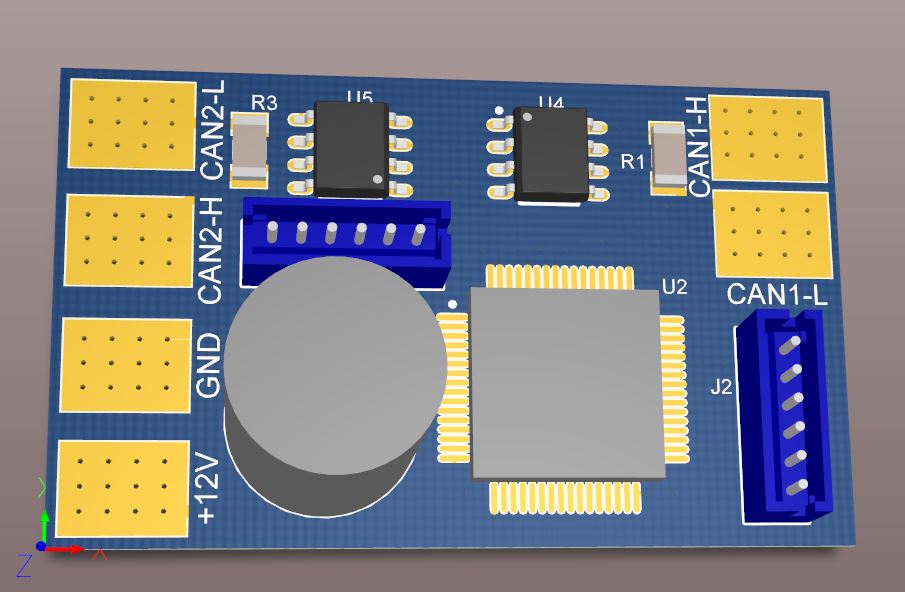
I designed a small PCB with an STM32F4 (excessive, but sure to have plenty of power and cost isn’t really an issue here). This has two CAN transceivers and a serial port for diagnostics.
I wasn’t sure quite what the protocol was going to be and went into it knowing that some protocols might not really allow this hack to work well. I put a script on that forwarded CAN messages over a crude UART communication channel and a VB app that downloaded them for display.
The sway bar runs on the CAN drivetrain network. This of course constantly has lots of bus traffic and changing messages so I needed some way to filter out the traffic. To do this I setup the VB app to be able to filter out any byte that is changing over a given time span. First start scanning for changing messages, leave it for 30 seconds, then turn off the filtering. At this point all the random messages containing various engine stats are filtered out. Press the sway bar button and watch for new changing messages. Sure enough, all that’s actually being transmitted to the sway bar is a button-press or button-release signal. If the sway bar connector was attached to the vehicle, there was also a response message indicating that the sway bar successfully disconnected. Now I knew that CAN ID 0x325 byte 6 contained the state of the sway-bar button, and that likely any message transmitted from the sway-bar should just be forwarded to the Jeep.
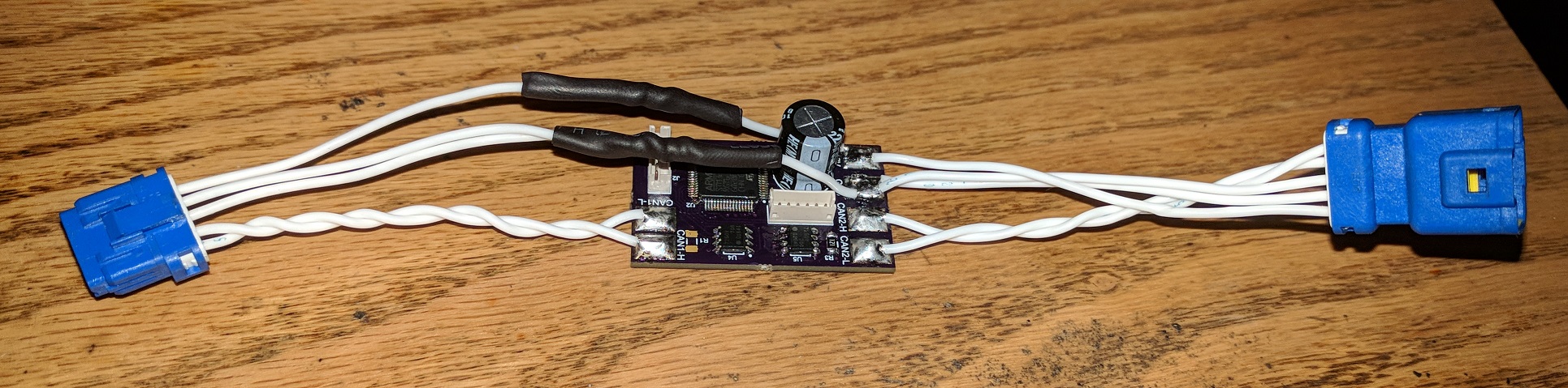
Now I cut the CAN wires going to the sway bar and put my board in-between with the vehicle on CAN1 and the sway bar on CAN2. Since I now knew the CAN addresses and bytes containing the control button as well as the response telemetry packet from the sway bar, I figured I’d start by trying just forwarding these messages and ditching all the other CAN traffic.
Unsurprisingly, this did not work. The sway bar didn’t respond to the button press at all and remained locked. The sway bar needs to be receiving vehicle speed information to know when it’s safe to stay disconnected. First I tried taking a snapshot of all the messages on the bus and sending them all out periodically, figuring it would emulate a Jeep going 0MPH in 4WD. This also did not work, although I knew some variation of this had to work since if the Jeep is properly emulated the sway bar must work. It ended up being that the message timing was fairly important. I found a dominant telemetry loop speed (I think it was around 10hz) and every time one of those messages appeared on the CAN1 port, I send out the dummy message set on CAN2 port. When the timing exactly matched up with what the sway bar was expecting, it worked! I used trial-and-error to determine exactly which of the roughly 40 CAN messages were actually needed for the sway bar to remain locked. It turned out only two messages were necessary, 0x428 and 0x215. I just stored a snapshot of the Jeep going 0MPH in 4WD and used those messages. I don’t actually know what these messages are, but presumably one is speed and one contains the 4WD shifter position.
I got lucky in that all the logic on whether or not the sway bar should be connected or disconnected resides in the sway-bar module itself. I was actually surprised by this since if I were designing this system I would keep the sway bar as simple of a module as possible and put the lock/unlock safety logic in the main vehicle computer. Fortunately, that’s not how the engineers at Jeep decided to solve the problem which made it fairly easy for me to hack. Had the logic been in the main computer, this wouldn’t have worked so well since the Jeep would send out a re-connect packet whether I like it or not, there’d be no relevance to emulating a Jeep at low speed.
I’ve had this in for many months and never had a problem with it. I can now disconnect the sway bar at any speed and in 2WD if I want.
Repo with code and board design: https://bitbucket.org/christensent1/swaybar/src/master/
How Do I FPGA?
I’ve been thinking about building stuff with FPGA’s for a while, and usually get turned away because FPGA’s are considerably harder to implement than microcontrollers since they have no on-chip memory. It is necessary to re-program the gates every time they power up, which requires an external flash memory chip. There aren’t great references online for the DIY community, so I figured I’d post how to get this working. Not using dev boards opens a world of opportunities, so I’m a proponent of not using Arduino’s and their FPGA equivalent for too long (sure, they’re good to get started with, but don’t become dependent)
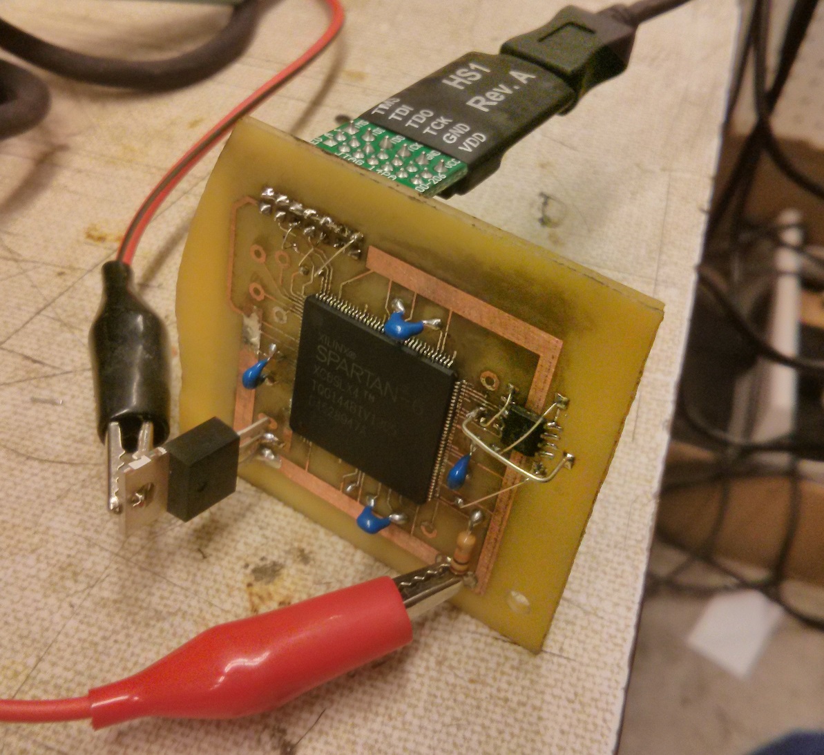
Not wanting to screw up an expensive complex board by being a first-timer at putting an FPGA into a circuit, I figured I’d build a little test board with the cheapest Spartan 6 you can get (about $10), which comes in a solderable TQFP144 package. Sadly, most high end FPGA’s are BGA and therefore quite hard to solder as a DIY project.
There are quite a few ways to program an FPGA. The most common would be direct programming, indirect programming, and processor programming. Direct programming is where there is a PROM chip which is programmed over JTAG, and the PROM chip programs the FPGA at boot. Indirect programming is where there is a PROM chip attached to the FPGA, and JTAG also connects to the FPGA. In this scenario, JTAG can either directly program the FPGA, or load a temporary PROM-programmer application onto the FPGA which programs the PROM and then restarts. The operational differences are subtle, but the circuit is quite different. Processor programming is where a microcontroller on the board performs the task of programming the FPGA, which would require custom code in the microcontroller as well as requiring you to have a micro at all. While substantially more advanced, this is way more powerful because the microcontroller can dynamically reprogram the FPGA on the fly for different tasks.
For this project, I’m going to use indirect programmimng, because it’s about $8 cheaper than direct programming, and processor programming is vastly overcomplicated for what I want to do.
The first task is to select a PROM chip. There are a number of series that are recognizable by the XILINX iMPACT tool. The M25P series is cheapest and very popular. You’ll need to read the datasheets to figure out how much memory your FPGA needs. I’m using the Spartan LX9 in my production board (although LX4 on this test board since it’s half the price), so I selected a 4M PROM. The M25P40 is only 67 cents on digikey in qty 1!
I’m using the Digilent JTAGHS1 programmer, since it’s the cheapest programmer that’s guaranteed compatible with Xilinx iMPACT (the programming application provided in ISE, the Xilinx IDE). At $55, it’s not the cheapest thing but you only have to buy it once and it’s way cheaper than the Xilinx brand programmers.
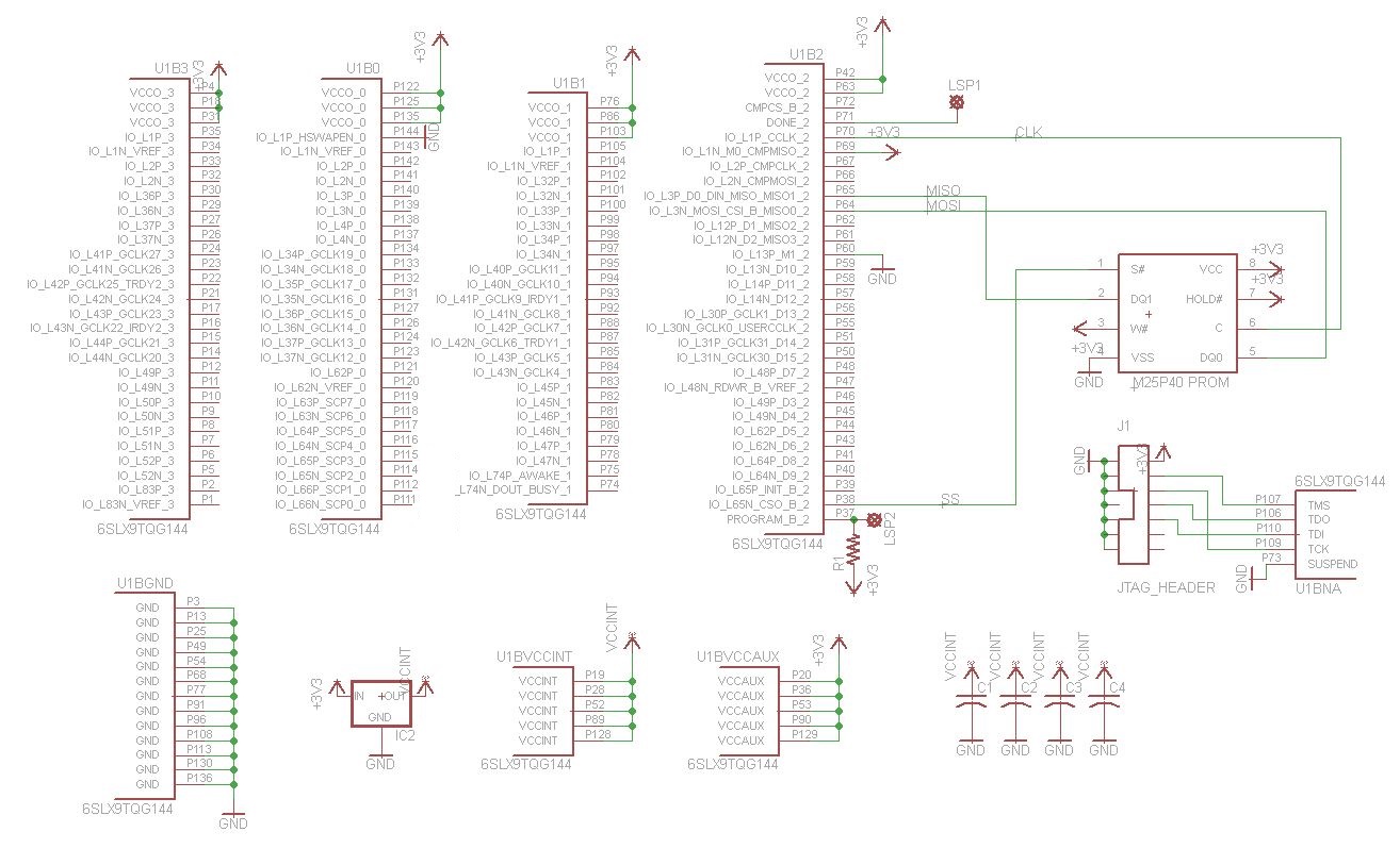
Here is the minimum schematic to hook it up to a Spartan 6 for JTAG programming. Other micros will have slightly different configuration bits, but the concept will be the same:
P144, HSWAPEN, if low enables a pullup resistor on all pins during configuration so any tristate devices are defined. You’d probably want to do this.
When P69 M0 is high and P60 M1 is low, the chip is configured for indirect programming over JTAG. Other M-configurations would be for other programming modes such as direct programming. For other chips, you’ll just have to look up whatever configuration bits your chip uses.
P37, PROGRAM_B_2 is the main chip reset pin. It should be pulled up, and to reset pulled low.
P71 DONE is a “done programming” output indicator provided for convenience.
TMS, TDO, TDI, and TCK are the JTAG pins, which just get hooked up to your programmer.
CLK, MISO, MOSI, and SS are the SPI data lines to the PROM.
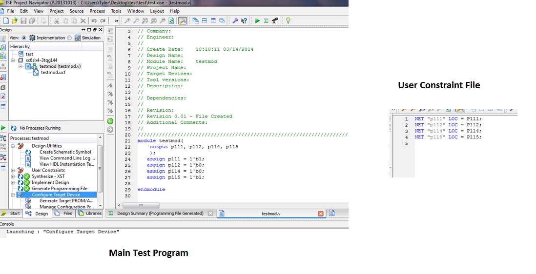
While this guide isn’t meant to be a “how to program for FPGA’s”, I’ll include my test script here, which just sets a few pins to test out the programming. The user constraint file tells the compiler what pins connect to what module IO lines:
Now, after generating the programming file, select configure target device from the process list and iMPACT will load. To just program the FPGA over JTAG without worrying about the PROM, select Boundary Scan, right click, select Initialize Chain, and if the FPGA is connected it should almost instantly detect it. You’ll then be prompted for a BIT file to program it, or you can right click the symbol for the chip and select a file that way. It’ll also prompt you to ask if you want to generate a PROM file. If you’re just loading the chip once, click no. Right click the symbol, hit program, and it’ll program the FPGA.
Now, if we want to make the program persistent on the FPGA, we need to program the PROM which is only slightly harder. This time, select yes to make a PROM programming file or alternatively select “Create PROM File (PROM File Format…)” from the iMPACT Flows list. This will start the PROM File Formatter:

In this window, we tell iMPACT exactly what to make as a PROM file. In this case, we’re using the M25P chip which is SPI flash (but not Xilinx Flash/PROM, which is for direct programming). Next select the storage size, in my case 4M. Finally, give it an output file name, and select OK. It should ask you for a BIT programming file, which is the programming file that you otherwise would have sent directly to the FPGA. It’ll then ask if you want to provide another BIT file for a second FPGA (you can program multiple FPGA’s off of a single PROM chip). If you just have one like me, select no.

An easy to miss step is to select Generate File from the iMPACT Processes list. When you do this, it’ll actually make the PROM programming file (I think it was .mcs? I forget). Now you can go back to Boundary Scan, right click the FPGA, and add the PROM file. A FLASH module should be appended to the diagram, which you can right click and Program:

That’s it! Now every time you turn on the board, it will auto-program off of the PROM. If you want to change the program, just repeat the process of uploading a new PROM file.
I’m Blogging!
I haven’t blogged in 14 months! This is not acceptable! I’m sorry Charles!
Let’s see what I’ve been doing in the last 14 months…
I continued making better and better electrostatic headphones
The art of stretching 1 micron and 2 micron mylar film for electrostatic membranes:

MITERS got new drill bits and end mills:

I finished my DIY SR-007 headphone clones, version 1

Went home for January and climbed a bunch of mountains


Came back to Cambridge, and built my Mini-electrostats… they didn’t sound very good, I dismantled them and deemed it a poor design

Then there was a huge snow storm (just barely not a blizzard, technically) in Boston where we got 3 feet of snow
With only a week left in the calendar winter to check it off the list, rented a car and did a midnight solo of Mt. Washington

I finished my SR-007 clone DIY headphones, version 2

Then I went back to Washington and worked at Boeing for the summer designing pulsed power electronics stuff in the physics applications lab. On the weekends, I climbed lots of awesome peaks. Now have 3/5 of Washington’s volcanoes checked off the list (Baker, Adams, and Glacier Peak [the best peak in Washington])


And had a mountain goat wander by while I had my camera out
Came back to cambridge, and MITERS GOT A CNC MILL!!!!
… so I used it to make DIY Sennheiser Orpheus clones, which sound spectacular. They are still a work in progress

Learned how to analog in 6.301

Experienced 100+MPH wind and -40F windchill in a fruitless solo endeavor on Franconia Ridge

Brought my DIY headphones and Blue Hawaii to New York for a head-fi meet

Ok I’m going to stop procrastinating and get back to studying. Only another week of classes and then finals!
Portable Electrostatic Headphone Amp
I’ll be going home for winter break, and don’t want to carry my big electrostatic amplifier, so I decided to make a Class-D portable amplifier.
Here are a few schematics… Eagle is too much of a pain to make nice schematics, so I’m not going to post a full schematic at this point.
Output stage:

Input stage:

Aside from the actual amplification stage, I need to make 

Tests show it working fairly well, although it draws quite a bit of no-load power. I attached a BJT as the load so I could vary the output current to plot efficiency vs. output, which resulted in the following data:

I fit the equation

which represents a constant controller current (including core losses with the output load of the feedback resistors). This fit results in a controller power draw of 1.25
With summer comes another few weeks at home to spend time in the mountains (and in the snow since it was a pretty heavy winter for snow so lots still around).
All trips were solo, just the way I like it!
First up, Mt. Daniel (7/21/2012):
A failed summit but an awesome trip. Was feeling sick 1000ft below the summit, so I turned around. Still a great place, definitely will return sometime and probably make it a two-day climb.


Next, a quick run to Kendall Katwalk (7/24/2012):
Quite a bit of snow left for so late in the season. A number of very steep snow crossings before getting to the Katwalk, although there were good boot paths through everything. After the Katwalk, almost all snow covered.


Last, Mt. Adams before heading home to Boston (7/29/2012):
Did this one as a 2-day trip, and made it to the summit. Of course, the one thing I somehow forgot to bring was my camera since it was on the charger overnight. Oh well, iPhone will do!


Summer Audio Work
Summer is almost over with classes starting up again next week.
I completed my Blue Hawaii amplifier over the summer, made a number of prototype electrostatic headphones (working on a final version now), and built a tube phono stage.

I ended up having some thermal issues on hot days after a long on-time. I recently put a bunch of holes into the bottom plate and in empty space on the PCB to hopefully allow for convection to occur more. Hopefully that’ll help, won’t have a chance to test it until I get the new headphones finished.
")
")
As for the headphones, there was a lot of trial and error learning done there. I’m sure I won’t remember even half of what I had to figure out, but here are some details on that part of the project:
Electrostatic headphones operate by moving a thin charged film between two high voltage differentially driven stators. The distance between the stators is 1mm in my drivers, many retail headphones go even lower. This film has fewer resonances than a conventional driver, but it has one pretty severe resonance in the range of 100-300hz, since after all it is basically a spring and mass system. This resonance can be damped out by having a good seal between the driver and the listener’s ear. In fact, this drives the resonant frequency lower by creating that volume, but more importantly damps it. Below the resonance, however, there will be some bass roll-off if the resonance is too high. This means the tension of the film (in this case, I’ve been using both 2uM and 6uM mylar, will probably stick with 2uM) has to be low enough to keep that resonance low. But, the tension must be high enough to give it enough spring to not just stick to one of the stators. Since there’s only 0.5mm between the film and either stator, this provides the opportunity for the film to pretty easily stick if there isn’t enough tension to pull it back to the center.
The stators I made are 0.062″ FR4, which I manually drilled with a small drill-press using a perforated steel sheet as a drill template to ensure a clean pattern:

Through lots of trial and error, I found a good tension just above the point of instability where the film hit a stator and stuck. To accomplish the tensioning, I hang weights from the film as seen in this picture:

Frames are then glued down onto the film to hold the tension.
Next, these films must be coated in a partially conductive material to allow the placement of a charge on them. There are quite a few methods people use to accomplish this. I started out using a white-glue/graphite/water mixture which did work, but is somewhat hydrophilic which would not lead to long term reliability. I ended up using an Elvamide solution, which leaves a coating of nylon behind after drying which is just conductive enough to carry the charge out onto the film.
To accomplish this coating I have just been brushing it on, but in my final revision I am going to airbrush it on since I’ve had trouble getting a uniform coating with a brush. When the coating is not uniform and equal on both sides, it can lead to channel imbalances.
A mylar film glued to the frame and coated with Elvamide:

Next in the process was figuring out how to make a protection film for the inside. Since sweat can build up while listening, this could lead to moisture getting into the driver if run with no protective film. Initially I just put another tensioned mylar between the driver and the ear, but found that to cause bass dropoff (green without protective film, red with):

Having even enough tension to make the protective film structurally stable caused some amount of bass roll-off.
I noticed almost all retail electrostatic headphone drivers use a wrinkled material as the sweat protection screen, and figured I’d give that a shot. This seems to greatly lower the material tension, but allows it to still stay structurally rigid.

Success!

Over the last week or two, I’ve been learning solidworks to design some more reliable headphones. In this revision I will be making all parts by CNC (with the exception of the stators which have been drilled with more precision using a complete drill mask for all holes including mounting holes)

Blue Hawaii
I’ve been working on making a Blue Hawaii electrostatic amplifier (designed by Kevin Gilmore). I’ve spent a lot of work on the chassis which I built myself. I’ve been having some trouble with premature clipping in the amplifier which I still need to sort out, and also need to figure out why there seems to be bandwidth issues above 10khz. Other than that, the project is well on its way to completion.

Power supply board

To do toner transfers for double sided boards, I hold the papers up to a light and align them, then tape the papers together to form a sandwich, and slide the board in before transferring. I’ve never had it off by more than a quarter of a drill hole. Usually it’s practically dead on.


Amplifier board after populating

Constant current sources as plate loads

All the boards (bottom right is a slow warm-up for the filaments and a delayed B+)

Milling the heatsink for the back of the power supply to fit a mil-connector and IEC input

Heatsink after cleanup and painting

Since paint isn’t the best of a thermal conductor, I took the heatsink back down to aluminum where transistors will mount. Fastest way was to just mill the surface off.

Covers to go over holes for tubes to exit the chassis


The chassis is built by having bars at each corner that faces screw onto. These were milled to be exactly 90* angles on all sides, so just screw it together and it forms a perfect box.

Drilling mounting holes for the base plate. I laid out the parts in cad (something I rarely do) to get drill positions so I could get all this done before getting boards ready to position.

Power output and IEC

The nicest box I’ve ever made. All the aluminum panels were polished to near mirror finish with a slight texture
More to come as I put more work into the project.
Live MIDI Interrupter
I had a fairly crude monophonic interrupter built for big-coil operation, but I wanted to improve on its design. It had no software control over pulse width so every note had the same width, and of course polyphonics is more fun.
One critical design requirement was that I need hardware protection against the controller accidentally going CW, even if the microprocessor somehow screws up. This is relatively easy by using a 555 as a one-shot on each rising edge, then AND gating that to the actual signal so that if an abnormally high duty cycle (or more likely a duty cycle of 100%) is attempted, the one-shot will turn off at a pre-set time (determined by trimpot R4). It is worth pointing out that an inverter could be used to trigger the 555, which requires a downward-going edge to trigger. I chose to use a second microprocessor output since it saves on components (and I wanted as many gates buffering the output power as possible).
I also wanted to have a fixed oscillator in the interrupter so that I can still use it as an easy optical oscillator for bench testing coil controllers without the need to setup a MIDI device. I threw in another 555 for this. A SPDT switch on SV1 allows for selecting between MIDI or this fixed oscillator.

Another goal was to have the controller programmable over the MIDI interface to control parameters such as pulse lengths specific to note (allowing low notes to be on for a longer bang than higher notes), MIDI channel, and multipliers to control pulse width during polyphonic playback. This can all be programmed over SYSEX, a communication means within the MIDI protocol that is designed for flashing MIDI hardware with firmware or updates.
I put together a quick python script to allow for changing parameters, although I may make a GUI at some point.

This project was also the first time I’ve tried 0.4mm isolation on ground planes, which allows for ground planes to pass between pins of a DIP socket. It etched fine using the laminator for toner transfer. The etch precision is getting so good that I need to look into solder masks.
")
Laminator Etching
I setup a laminator at MITERS for etching a few months ago, but forgot to write about it until now. So here’s some pictures and a little info on the modifications to make it into a fantastic PCB etcher:
It is a GBC 9″ laminator (pretty cheap, $45 on amazon usually, I’ve heard you can get it for $10 or even less if you get lucky on sales or search around a lot). Out of the box, it’s an incredibly low quality laminator that can’t do much more than paper. If you put a circuit board through it, the gears in the motor strip themselves out and it quickly destroys itself. You can kind of force it to keep going by pushing the board in, but it’s totally not worth it after how great it performs with some modifications.
All I did was take it out of its case and put a new motor on it. I put a slower motor on, something like 2RPM instead of the stock 6RPM motor (I forget the exact numbers). You can’t really go too slow since you want lots of heat and pressure to get a circuit board to transfer well, and multiple passes aren’t ideal since it can lead to blurring if thin paper is used.
I threw together some mount brackets which weren’t quite strong enough to prevent the motor drive gear from skipping, so I made a little bearing to keep the motor shaft lined up with the gears. That prevents the gears from slipping away from each other, and it easily feeds standard PCB thicknesses.
The capacitor on the front is a motor start cap which is overkill in size for this motor, but it was laying around so why not use it.
Transfers come out 100%, every time. There’s no longer any guess work involved with the time and pressure of using a clothes iron. It makes it a real treat to etch boards.


